Sensors & Input/Output devices
A. Sensors on the phone
The first part of the assignment is to have an understanding of the applications of sensors we use daily and how they work. To learn abou this we used a Samsung Galaxy Note9 as our testing device. In every samsung phone there is a feature to access the various sensors and its data. This feature was accessed by dailing *#0*# on the dailer to open the sensor feedback page.
Listed down below are the various sensor data available for the user to inspect. We have also uploaded videos of its working.
B. Input device with Arduino - Ultrasonic sensor HC-SR04
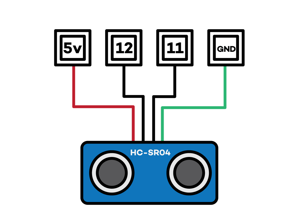
The Ultrasonic sensor has two parts to it - one for sending the signals which is the ECHO port and the other for receiving the signals which is the TRIG port. For receiving the data from the sensor we upload a pre designed ultrasonic library for the HC-SR04 sensor. Shown below is the connections for setting up the sensor.
These sensors an used to find tank levels and is commonly used for directional proximity sensing.
The code used for the sensor is as follows:
#include "SR04.h"
#define TRIG_PIN 12
#define ECHO_PIN 11
SR04 sr04 = SR04(ECHO_PIN,TRIG_PIN);
long a;
void setup() {
Serial.begin(9600);
delay(1000);
}
void loop() {
a=sr04.Distance();
Serial.print(a);
Serial.println("cm");
delay(1000);
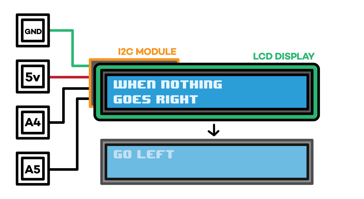
C. Output device with Arduino - LCD screen
The Ultrasonic sensor has two parts to it - one for sending the signals which is the ECHO port and the other for receiving the signals which is the TRIG port. For receiving the data from the sensor we upload a pre designed ultrasonic library for the HC-SR04 sensor. Shown below is the connections for setting up the sensor.
The Ultrasonic sensor has two parts to it - one for sending the signals which is the ECHO port and the other for receiving the signals which is the TRIG port. For receiving the data from the sensor we upload a pre designed ultrasonic library for the HC-SR04 sensor. Shown below is the connections for setting up the sensor. With the help of the I2C module, fewer pins are required to make connections to send data to the LCD display.
Codes used for this exercise:
#include <Wire.h>
#include <LiquidCrystal_I2C.h>
// Set the LCD address to 0x27 for a 16 chars and 2 line display
LiquidCrystal_I2C lcd(0x27, 16, 2);
//LiquidCrystal_I2C lcd(0x3F, 16, 2);
void setup()
{
// Robojax code for LCD with I2C
// initialize the LCD,
lcd.begin();
// Turn on the blacklight and print a message.
lcd.backlight();
// Robojax code for LCD with I2C
}
void loop()
{
//start of loop Robojax code for LCD with I2C
lcd.clear();
lcd.print("When nothing ");
lcd.setCursor (0,1); // go to start of 2nd line
lcd.print("goes right ->");
//lcd.print(millis() / 1000);
delay(3000);
lcd.clear();
lcd.print("Go left <-");
//lcd.print(millis() / 1000);
delay(3000);
//end of loopcode Robojax code for LCD with I2C
}
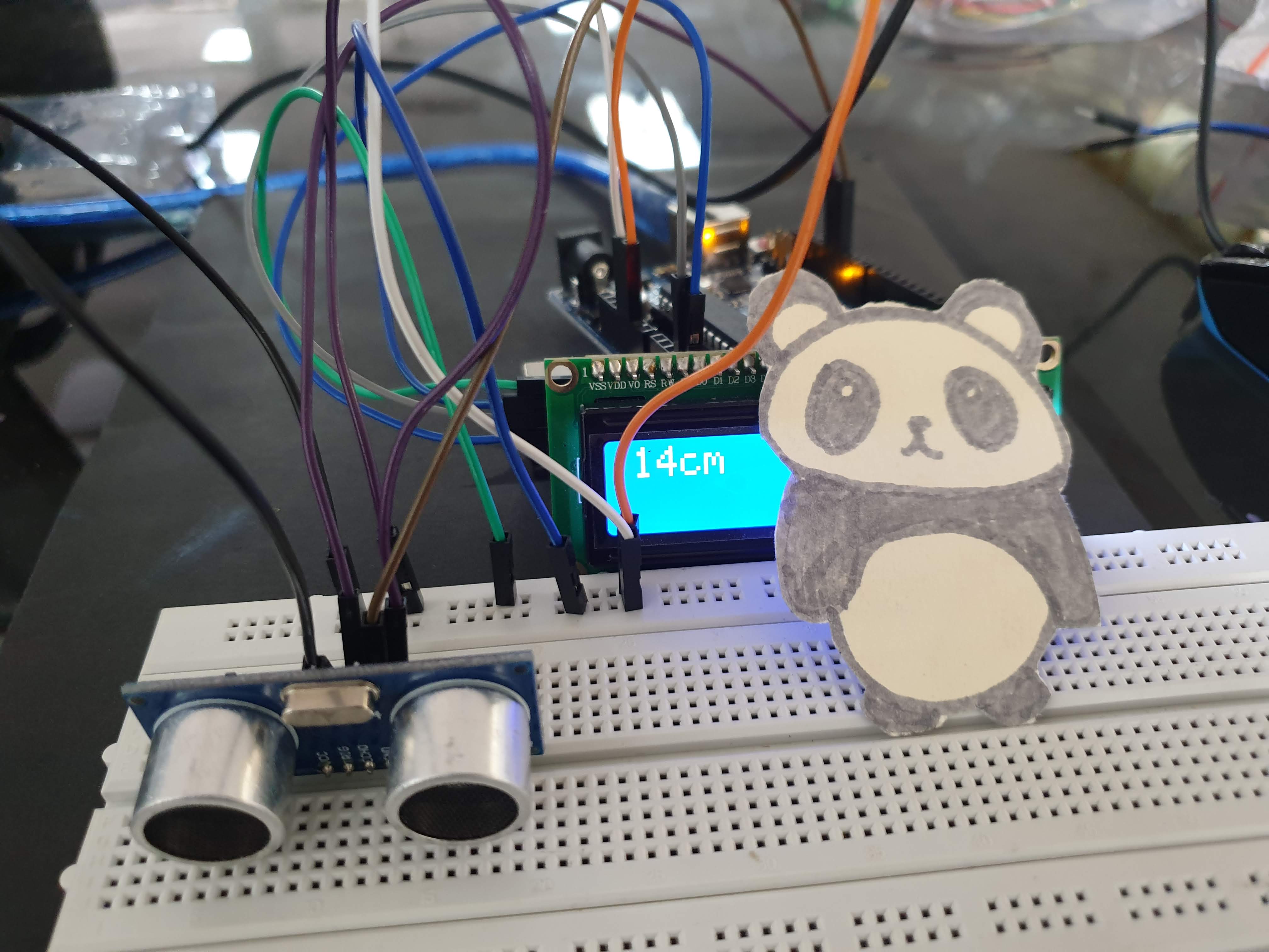
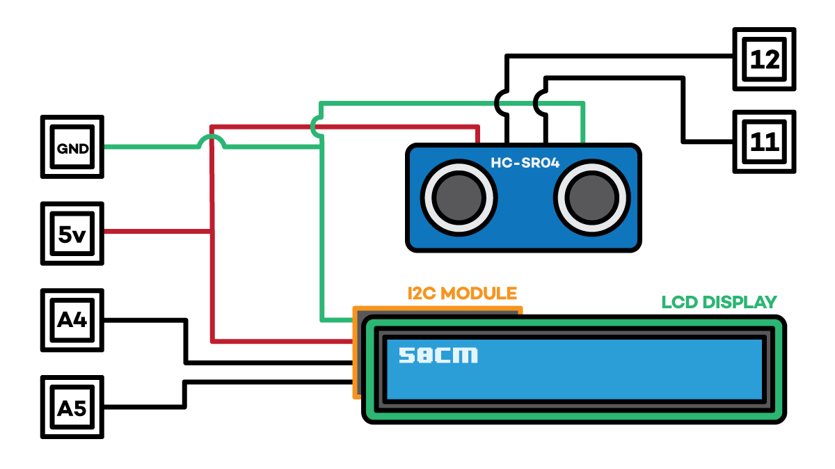
D. Using both input and output devices with Arduino
In this exercise we used a LCD screen to display the proximity data recieved from the ultrasonic sensor.
Code used for this experiment:
#include <SR04.h>
#include <Wire.h>
#include <LiquidCrystal_I2C.h>
LiquidCrystal_I2C lcd(0x27, 16, 2);
#include "SR04.h"
#define TRIG_PIN 12
#define ECHO_PIN 11
SR04 sr04 = SR04(ECHO_PIN,TRIG_PIN);
long a;
void setup() {
Serial.begin(9600);
delay(1000);
// Robojax code for LCD with I2C
// initialize the LCD,
lcd.begin();
// Turn on the blacklight and print a message.
lcd.backlight();
// Robojax code for LCD with I2C
}
void loop() {
a=sr04.Distance();
lcd.clear();
lcd.print(a);
lcd.print("cm");
delay(500);
}
Thanks to Sonsy for assisting with the video